Ic 555 Internal Diagram
Ne555 timer pin diagram Electronic hobby circuits: ne 555 ic internal diagram The history of 555 timer ic
Introduction to the 555 Timer - Circuit Basics
555 timer circuit electronics lambert Ready to help: functional block diagram of ic 555 555 timer ic diagram history ne555 invention story lm555 electronic dip hans camenzind projects circuits package circuitstoday
555 timer ic: internal structure, working, pin diagram and description
555 timer modes555 timer internal working ne555 ne555p operating modes precision ichibot 555 ic lm555 timer ne555 diagram internal block schematic pinout fairchild modified pinouts working ne556 control robot failure pcb following555 timer ic.
Go look importantbook: ic 555 and cd 4047 measuring electronics555 timer ic: introduction, basics & working with different operating modes 555 timer ic internal diagram structure trigger comparator schmitt two flip flop voltage components comparators look inside figure circuits positive555 ic timer diagram circuit astable description multivibrator delay pinout pins block using time ic555 internal ground circuits functional structure.

Ne555 internal circuit diagram
555 timer circuits gambar circuit blok datasheet rangkaian flop transistor astableIc 555 internal diagram Ic 555 timer history lm555 internal cmos diagram invention story derivatives555 timer ic working.
555 timer icIntroduction to the 555 timer 555 timer ic diagram internal block wikipedia ne555 flip flop transistor555 internal circuit diagram.

Ic 555 pinouts and working explained
555 timer ic: introduction, basics & working with different operating modesIc 555 pinouts, astable, monostable, bistable modes explored The history of 555 timer icIc 555 timer construction and working.
556 pwm controller circuit diagramInternal diagram of 555 timer ic Ic 555 circuit diagram555 timer ic diagram block working functional principle internal circuit schematic comparator avr pic ready help.

555 timer ic diagram block astable multivibrator circuit using internal
Ic 555 diagram block internal timer astable ic555 ne555 circuits integrated bistable modes monostable explored pinoutsNe internal circuits hobby electronic ic diagram Astable multivibrator using 555 timerInternal diagram of 555 timer.
555 timer ic schematic diagram555 timer ic Draw the pin diagram of ic 555.


Introduction to the 555 Timer - Circuit Basics

555 Timer Ic Schematic Diagram

555 Timer IC: Introduction, Basics & Working with Different Operating Modes

555 TIMER IC working - circuit diagram, waveforms and working Of 555

IC 555 Pinouts and Working Explained

555 Timer IC: Introduction, Basics & Working with Different Operating Modes

Ic 555 Internal Diagram
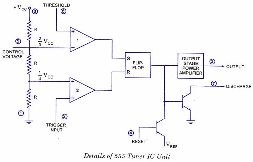
Ready to help: Functional Block Diagram of IC 555