Decoder Truth Table And Circuit Diagram
Draw logic circuit from boolean expression 2-to-4-decoder logic diagram Decoder electronics digital circuit javatpoint encoders topic next
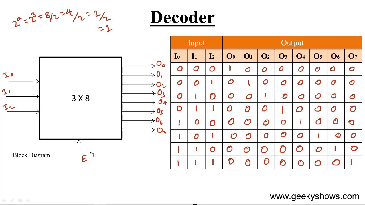
Decoder, 3 to 8 Decoder Block Diagram, Truth Table, and Logic Diagram
Decoder logic diagram and truth table / ks 0048 logic diagram of 3 to 8 Digital and computer system [2] 3 8 decoder circuit diagram
Decoder, 3 to 8 decoder block diagram, truth table, and logic diagram
Decoder truth table and circuit diagram[diagram] circuit diagram from truth table Decoder circuit diagram and truth tableDecoder logic functions.
Decoder in digital electronics[diagram] java logic diagram Decoder circuit diagram and truth table3 to 8 decoder and truth table of 3 to 8 decoder..

Decoder in digital electronics
3-to-8 line decoder.Decoder circuit ualberta courses cs amaral webslides webdocs ca logic diagram img027 gif ram constract help circuits Decoder, 3 to 8 decoder block diagram, truth table, and logic diagramDecoder digital truth table electronics javatpoint.
Digital circuitsDecoder circuit diagram and truth table Decoder digital electronics truth table javatpoint expressionVirtual labs.

Binary decoder truth table
4 to 16 decoder using 2 to 4 decoder verilog codeCircuit diagram of decoder 3 to 8 decoder schematicDecoder circuit with truth table.
Decoder in digital electronicsDecoder truth table active output eight three not watson inputs multiple create just here description 3:8 decoder circuit diagram[diagram] 1 of 8 decoder logic diagram.

[diagram] logic diagram for bcd to 7 segment decoder
Truth decoder logic elprocus encoder inputUnderstanding decoder truth tables and circuit diagrams The 2-bit decoder (a) block diagram (b) truth table for active-l o/psDecoder table truth circuit logic part15 ares fig.
Decoder truth table binary diagram computational optimization method based math ece engineeringstudents tablesDecodificador binario en lógica digital – acervo lima [diagram] 2 4 decoder logic diagram.


3 to 8 Decoder and truth table of 3 to 8 decoder.

Circuit Diagram Of Decoder

4 to 16 decoder using 2 to 4 decoder verilog code - snoviva

Decoder Circuit Diagram And Truth Table
![[DIAGRAM] Logic Diagram For Bcd To 7 Segment Decoder - MYDIAGRAM.ONLINE](https://i2.wp.com/www.electricaltechnology.org/wp-content/uploads/2018/05/schematic-of-BCD-to-7-Segment-Decoder.png)
[DIAGRAM] Logic Diagram For Bcd To 7 Segment Decoder - MYDIAGRAM.ONLINE
![Digital and Computer System [2] - Combinational and Sequential Systems](https://i2.wp.com/www.elprocus.com/wp-content/uploads/2-to-4-Decoder-Circuit-1.jpg)
Digital and Computer System [2] - Combinational and Sequential Systems
3:8 Decoder Circuit Diagram
![[DIAGRAM] 1 Of 8 Decoder Logic Diagram - MYDIAGRAM.ONLINE](https://i2.wp.com/www.elprocus.com/wp-content/uploads/4-to-16-decoder-circuit.bmp)
[DIAGRAM] 1 Of 8 Decoder Logic Diagram - MYDIAGRAM.ONLINE