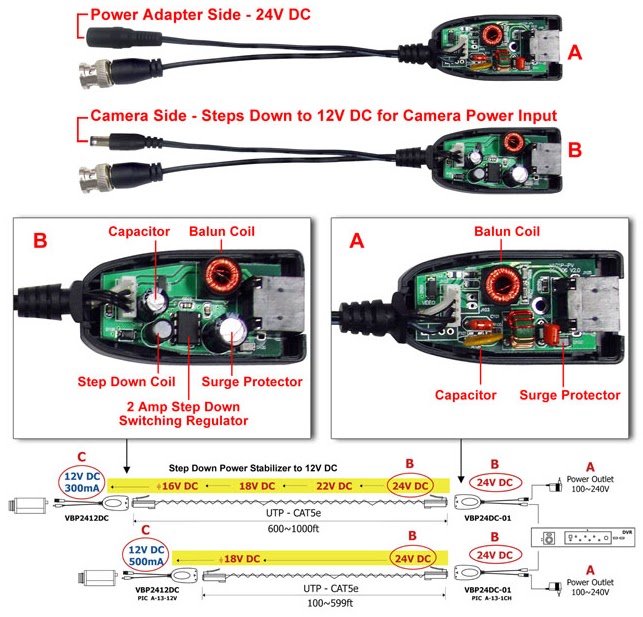
Audio Balun Circuit Diagram
Video over utp – commercial balun circuit Balun qro dxzone antennas indoor baluns ferrite bal fb un type made Circuit schematic of the proposed active balun.
4:1 QRO Balun : Resource Detail
Audio balun circuit diagram Cctv balun wiring diagram Balun cat5 wiring cameras baluns cctv cctvcamerapros
[diagram] cctv balun wiring diagram
Cctv balun diagram wiring circuit baluns schematic dvr learn kabelWikkelen rf trafo Audio balun circuit diagramCircuit schematic of the proposed active balun..
Balun switchable switch qrp fr ratios flipBalun circuit schematic Balun circuit diagram postcardBalun schematic proposed.

Balun hf build own radio antenna amateur coaxial baluns enthusiast electronic ham antennas
4:1 qro balun : resource detailBalun 868mhz Performance of balun circuit: (a) schematic circuit diagram of theAudio balun circuit diagram.
Balun utpVideo over utp – commercial balun circuit Block diagram and schematic of the proposed balun.Balun guanella current radio step construction qrp iw5edi type ham next.

1:1 balun for hf frequencies(λ/2 dipole)
Balun diagrama qsl homebrew lu9dpd bobinado núcleo toroidal prestadoStereo audio balun examples of a setup Balun schematic circuitBalun voltage wiring antenna figure baluns choose board.
Balun ferite 30mhz diagrams usingHow to use a video balun and cat5 cable for cctv cameras Balun utpAudio balun circuit diagram.
![[DIAGRAM] Cctv Balun Wiring Diagram - MYDIAGRAM.ONLINE](https://i2.wp.com/diagramweb.net/img/wiring-diagram-hf-balun-9.png)
Balunes centros de dipolos y aisladores
M0pkzEa4eoz, an amateur radio electronic enthusiast: build your own hf balun Balun 1:1 4:1 switchableBalun dipole hf frequencies.
Balun 4:1 rf trasformerTransformer baluns unbalanced circuits balanced brats secondary radio mar post Balun schematicCat5 balun wiring diagram.

Lc baluns in action – robust circuit design
Circuits of 1:1 and 4:1 transformer balunsFerite balun 1.8 Step-by-step construction of a 4:1 current-type balunElectronic – explain how this cctv video balun actually works.
Balun circuit 868mhz circuitlab filter descriptionLc balun circuit differential single baluns action Balun wiring diagram power cctv wire cat5e coax wires cameras cctvforum baluns ptz each installation use insert stripping simply intoBalun circuit diagram postcard.
Video balun wiring diagram
Balun unun antenna qrp tuner inverted ohm trasformer rf officinahf setup benvenuti disclaimer .
.


Stereo Audio Balun Examples of a Setup

4:1 QRO Balun : Resource Detail

Circuit schematic of the proposed active balun. | Download Scientific

Block diagram and schematic of the proposed balun. | Download

Circuits of 1:1 and 4:1 transformer baluns

Cat5 Balun Wiring Diagram - Wiring Flow Schema